1. Getting Started
The following sections describe how to begin using ANSYS Composite Curing Simulation (ACCS):
ACCS is developed by LMAT Limited and distributed by ANSYS Inc. More information about simulation of composites can be find on ANSYS Composite Materials.
1.1. Overview
The following sections provide an overview of ANSYS Composite Curing Simulation (ACCS).
1.1.1. Introduction
This document presents ANSYS Composite Cure Simulation developed with the objective of improving product performance by eradicating manufacturing defects as well as lowering risk associated with complex processes. It can be used in a variety of different applications where both, thermosetting and thermoplastic polymers are used.
During the curing process of thermoset polymers the materials undergo phase changes, exothermic reactions and chemical shrinkage. The cross linking of the polymer chains is a chemical, irreversible process. In thermoplastics on the other hand, the polymer chains are bonded by intermolecular forces at lower temperatures. These forces weaken with raising temperatures and subsequently the thermoplastic material can be reshaped if there temperatures are high. As opposed to thermosets, this process is reversible. For both thermosets and thermoplastics the final cooling of the material leads to additional shrinkage. The materials changes in phase, density and volume might appear at different times in a part during its manufacturing process. This inhomogeneous curing and cooling might lead to residual stresses, process induced distortions (PID), excessive heat due to exothermic reactions followed by local material deterioration etc.
In some cases runaway exothermic reactions or residual stresses are the cause for parts which are structurally damaged before ever seeing external loading. It is often seen, that residual stresses lead to cracks in polymer parts but also in coatings and filling applications where it is of utmost importance that no cracks appear.
Even if the parts are not damaged per se, distortions from their as-designed shape may cause problems during assembly, significantly increasing overall product cost as well as its in-service performance. Currently tool designers account for the process induced distortions based on their experience and often approach the problem using trial-and-error techniques. Although this can give good results for parts of relatively simple geometry, with increasing demand on the composite part complexity, more sophisticated models have to be introduced which can help to predict tooling geometry required to consistently produce structures of high-quality within tight dimensional tolerances. The predicted distortion of the composite part can be used to compensate the tooling geometry or design the assembly process resulting with the minimal built-in stresses. The application of numerical simulations for polymer manufacturing processes has the potential for reducing process development cost and increasing the overall product quality.
In the light of its complex nature, it is evident, that the outcome of a curing process is hard to predict and that experience falls short in many cases. In these cases ANSYS Composite Cure Simulation (ACCS) helps the engineer to simulate curing problems and to understand the manufacturing process in detail.
ACCS enables the engineer to simulate:
The curing process and its phase changes, reaction heat and material state
Process induced distortions
Development of residual stresses
Tool compensation
1.1.2. ACCS Workflows
ANSYS Composite Curing Simulation (ACCS) is an extension to ANSYS Mechanical and is integrated with the Transient Thermal and Static Structural Analysis Systems. As a result, the entire workflow for analyzing the cure of a composite structure or any other structure that involves resin systems or thermoplastics can be completed from design to final production information.
The solid geometry of the tooling surfaces of a composite structure or of a pure resin part is the basis for analysis and production. Based on this geometry and a FE mesh, the boundary conditions and composite definitions are applied to the structure in the pre-processing stage. After a completed solution, the post-processing is used to evaluate the performance of the design and cure related results. In the case of a tool compensations or a change in a process parameter or material, the geometry, the cure cycle or the material must be modified, and the evaluation is repeated.
1.1.3. Supported Platforms and Functional Add-ons
The ANSYS Composite Cure Simulation add-on requires a copy of ANSYS to be already installed. You will also need administrator rights to be able to install this add-on. Currently, the Workbench integration is only available for Microsoft Windows machines. Windows 7, 8.1 and CentOS 6.X are not officially supported.
1.1.4. First Steps
The best way to get to know ACCS features is to attempt one of the workshops. There are four workshops that explain step-by-step how to define and analyze basic cure simulations and one that shows the workflow to compensate a tool geometry. The workshops start off with existing Workbench projects. These sample projects and more information can be found in section Workshops. Knowledge of ANSYS Workbench is a prerequisite.
For information on how to build a composite model from new, see the Usage Reference.
Best Practices offers an insight into modeling approaches for common cure simulation problems. Background information on the underlying theory used in ACCS is available in Theory Documentation. This is especially of interest for the analysis of exotherms and Process Induced Distortions (PID).
1.2. Graphical User Interface
The user interface is the same as in Mechanical. When the ACCS extension is installed, a new ribbon is added in the Mechanical menu bar.
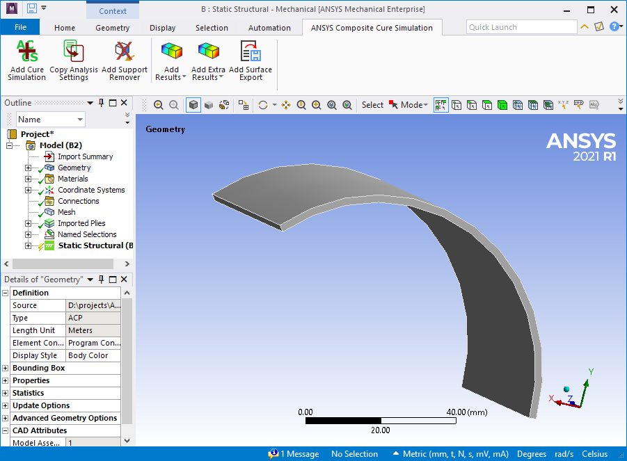
Fig. 1.1: ANSYS Composite Curing Simulation Ribbon in the Mechanical GUI.
1.3. Workbench Implementation
ACCS is fully implemented in ANSYS Workbench and therefore supports the standard Workbench workflows. This is includes the ANSYS composite Pre-Processing tool ACP for long fiber composites and external model to work with external data. For Composite parts, in Workbench, ACCS can be used together with the ACP analysis component, that can be used from basic analysis to complex load cases and analyses. The following sections contain some examples of common use of the ACP analysis system.
1.3.1. Basic Workflow
For composite structures, ACP Prep is the ANSYS tool for the build up of the reinforcement structure. For pure resin structures the workflow will not consider this system. A composite shell defined using ACP can be imported into Mechanical for analysis by importing the mesh and composite definitions from an upstream ACP system. To import a composite shell from ACP into Mechanical, use the following procedure:
Make sure you have the ACCS extension activated by checking it in the Extension Manager in Workbench.
From the Component Systems list, drag and drop an ACP (Pre) system (or another Mechanical System) nto the Project Schematic.
Define the Material. For more information on Cure Material Properties available in Workbench, see the section :ref:’Material Definition’ of this User’s Guide.
Select the Geometry cell and specify your geometry. Make sure that you properly define your mesh, Named Selections, etc. before opening the geometry in ACP or direct in Mechanical. Note that ACP only uses a linear or quadratic shell mesh.
Perform all the steps to fully define your ACP (Pre) system.
Return to the Workbench. Drag and drop a supported Mechanical system into the Project Schematic.
Drag and drop the ACP (Pre) Setup cell onto the Mechanical system Model cell to create a solid transfer of the model. The connection enables the transfer of Mesh, Geometry, Engineering Data, and composite definitions from ACP to Mechanical. When you create this link, the Geometry and Engineering Data cells no longer display for the Mechanical system. ACP provides this system data.
Define the Boundary Conditions together with the cure cycle in the Mechanical System.
Add the ACCS feature “Add Support Remover”.
Activate the cure simulation Equations by selecting Add Cure Simulation in the ACCS ribbon.
Post-Process the results with the cure simulation specific result options of ACCS.
1.3.2. ACCS Component Properties
The following section describes properties of an ACCS Component in Workbench. ttr og The ACCS solution is integrated within Workbench in the form of an additional toolbar as show in the figure below.

Fig. 1.2: ACCS toolbars available in Workbench.
Fig. 1.3:allows the user to update the material properties from Engineering Data.

Fig. 1.4: allows the user to homogenize the glassy properties when defined as fiber and matrix. It is used to upgrade Workbench projects to the ANSYS version 2020R2. It is only necessary at the beginning of the import.
1.3.3. Supported Analysis Types
As ACCS is an ACT extension of Mechanical it is present in all the Mechanical Systems. But where it really make sense to use is in the Transient Thermal and Static Structural Analysis Systems. Because with those Systems the cure cycle is simulated.
1.3.4. Multiple Load Cases and Analyses
Complex workflows with multiple load cases and/or analyses are defined in the same way as standard analyses. In most of the cases, the links to share the data are set automatically by Workbench. Some links must be manually added. In the following example, the links from the Solution cells of analyses D and F to the ACP (Post) system have been added manually.
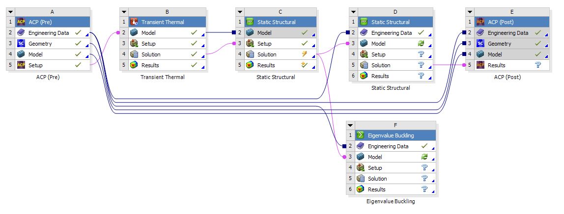
Fig. 1.5: multiple Load Cases and Analyses