What's New in Mechanical at 2019 R2?
Play a video describing the new features:
Click any topic below for more information:
|
Interface Enhancements Major Analyses |
Analyses (continued) Loading and Support Conditions Graphics Solution and Results |
External Model Contact and Connections General |
|
Helpful Links These are for your convenience. They require internet access and will open in a new browser window. Some also require Customer Portal login credentials. |
|
"What's New" for Other Mechanical Releases Use these to easily see the "What's New" pages for other releases of Mechanical. Use these same links to return to this "What's New" page.
|
New Ribbon Toolbar
To help you work more quickly and more efficiently, the ANSYS Mechanical application now organizes its tools and commands using a contextual ribbon in place of drop-down menus and multiple parallel toolbars. This new organization uses tabs to group similar commands together, making the interface faster to use, more intuitive, and more helpful.
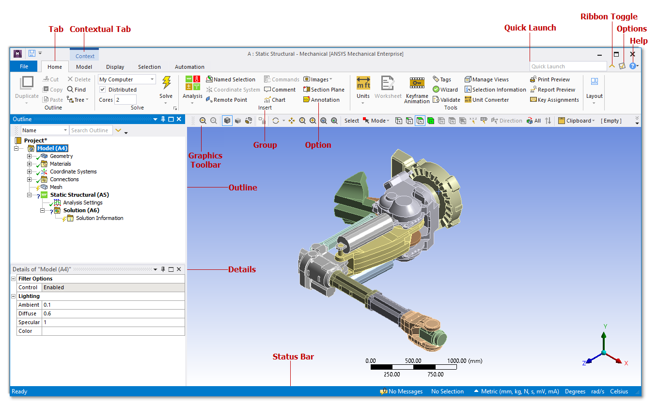
Major components of the new ribbon toolbar at 2019 R2.
 Want to learn more? If you are on Windows, go to
the documentation for this topic.
(Requires internet access and will
open in a new browser window. Not for Linux platforms.)
Engineering Data in Mechanical
A new Assignment panel in Mechanical lets you assign a material directly from the Engineering Data libraries without being in the Engineering Data Workspace. You can quickly choose a favorite, recent, or project material, or you can search for a material in the libraries. When you select a material from the Materials folder in the Outline, you can view the data being used by Mechanical and also access edit capabilities in the Engineering Data Workspace.
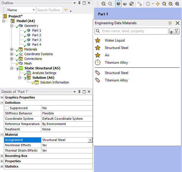
Materials from the Engineering Data libraries are accessible directly from Mechanical.
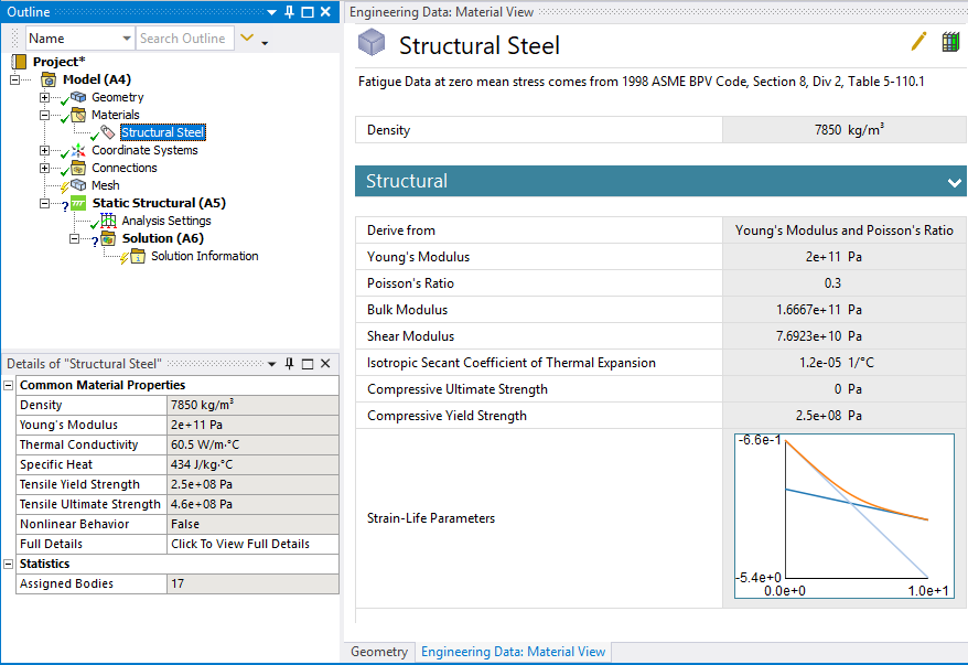
You can inspect the material properties used by Mechanical, and their values, as you browse the materials from within Mechanical.
 Want to learn more? If you are on Windows, go to
the documentation for this topic.
(Requires internet access and will
open in a new browser window. Not for Linux platforms.)
GRANTA Materials Data
The GRANTA Materials Data for Simulation product is available at 2019 R2 (in the Mechanical interface only).
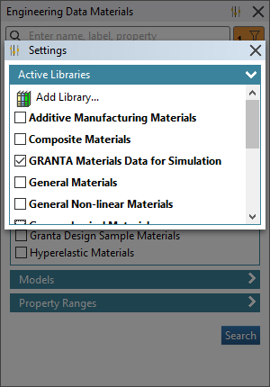
The GRANTA Materials Data for Simulation product are part of 2019 R2.
 Want to learn more? If you are on Windows, go to
the documentation for this topic.
(Requires internet access and will
open in a new browser window. Not for Linux platforms.)
Commands Object
Interface changes have also been made to the Worksheet used by the Commands object.
The Worksheet now:
- Provides an auto-completion drop-down menu (based on character entry) as well as a tooltip banner that displays the associated command arguments (Mechanical APDL Solver only).
- Provides a search feature using the Ctrl+F key combination.
- Includes line numbers.
- Displays hidden characters such as paragraph marks and spaces.
- Provides colored syntax highlights for entries such as fixed values, variables, comments, etc. (Mechanical APDL or Rigid Body Dynamics solvers only).
- Provides integrated zoom in and zoom out options. Previously, zooming was performed using the mouse wheel.
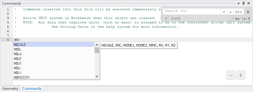

The Commands Object Worksheet.
There is also a new Command preference category in the Options dialog that lets you specify the default behavior of some of the above features.
 Want to learn more? If you are on Windows, go to
the documentation for this topic.
(Requires internet access and will
open in a new browser window. Not for Linux platforms.)
Major
NASTRAN File Export
For Static Structural and Modal analyses, you can now export your simulation as a NASTRAN bulk data (.nas or .bdf) file. You can therefore set up your simulation using the capabilities that Mechanical offers, then run the simulation with your choice of NASTRAN solver.
 Want to learn more? If you are on Windows, go to
the documentation for this topic.
(Requires internet access and will
open in a new browser window. Not for Linux platforms.)
Mixed-Dimension Analysis
Mechanical now allows combining two-dimensional (2D) and three-dimensional (3D) bodies in the same model. For shell bodies (only) defined in the X-Y plane, the Dimension property on the Body object lets you set the body as either 3D (default) or 2D. Mechanical then uses this property to write the appropriate element type (3D or 2D) to the input file.
 Want to learn more? If you are on Windows, go to
the documentation for this topic.
(Requires internet access and will
open in a new browser window. Not for Linux platforms.)
Fracture - Multiple Crack Support
Multiple Crack Growth using SMART Methodology
Mechanical now supports growth of multiple cracks present in the model using SMART methodology. This enables you to specify multiple cracks in the model and associate each crack with its respective SMART Crack Growth object.
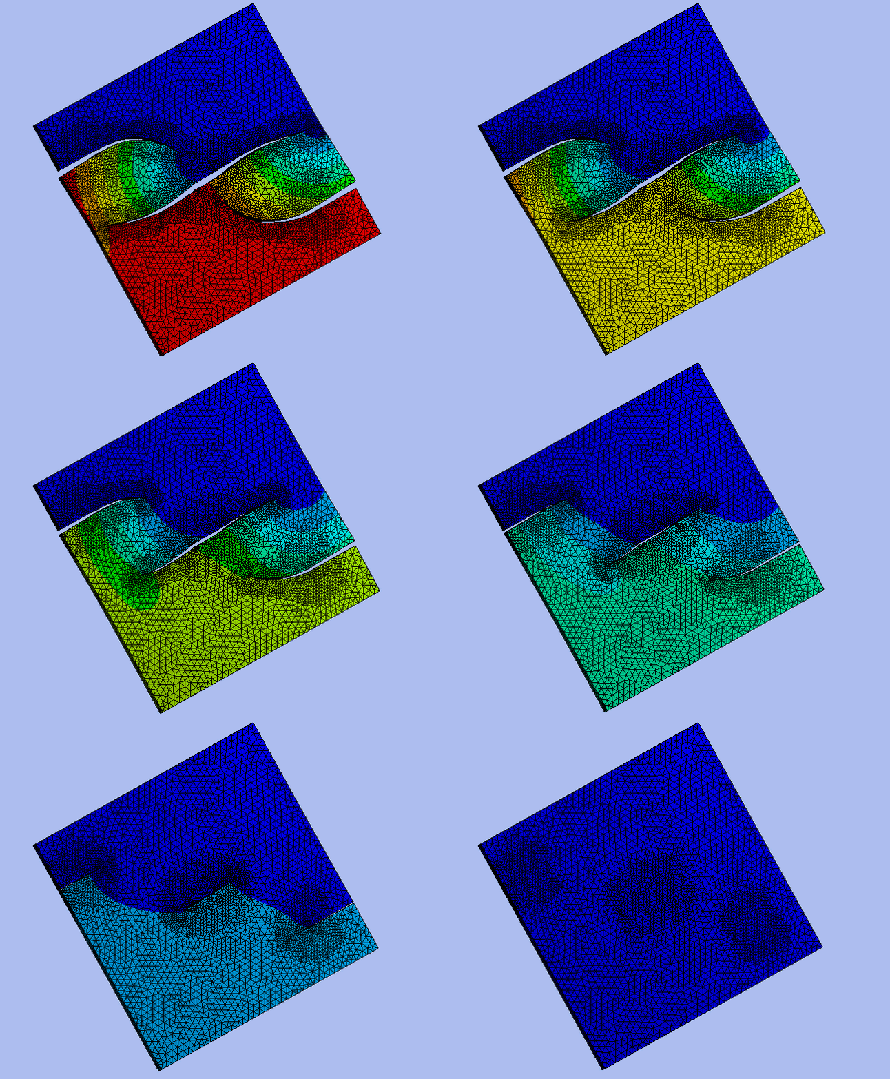
Progression of three cracks in a plate.
 Want to learn more? If you are on Windows, go to
the documentation for this topic.
(Requires internet access and will
open in a new browser window. Not for Linux platforms.)
Fracture Tool
The Fracture Tool now enables you to group results for multiple cracks using the new Crack Selection Mode property. The options for this property include Single Crack (default) or All Cracks. Single Crack behaves as in previous releases. All Cracks automatically groups the results of all the cracks you have defined on the model.
 Want to learn more? If you are on Windows, go to
the documentation for this topic.
(Requires internet access and will
open in a new browser window. Not for Linux platforms.)
Substructure Analyses
Condensed Part Worksheet
Now, when working in the Condensed Part Worksheet, you can select multiple table rows using either the Ctrl or Shift keys for the context (right-click) menu options Go To Selected Items and Delete.
 Want to learn more? If you are on Windows, go to
the documentation for this topic.
(Requires internet access and will
open in a new browser window. Not for Linux platforms.)
Workflow Enhancement
Mesh modifications made to parts of the model that are not contained inside of the Condensed Parts will not require re-generation of those condensed parts. However, there are mesh update exceptions for generated condensed parts. Applying the Mesh Edit, Element Orientation, or Mesh Numbering objects to your simulation causes up-to-date condensed parts to become obsolete and require regeneration.
 Want to learn more? If you are on Windows, go to
the documentation for this topic.
(Requires internet access and will
open in a new browser window. Not for Linux platforms.)
Condensed Part Generation
The condensed part generation process now supports Distributed ANSYS. When you generate condensed parts, the application uses the settings of the Distribute Solution and the Max number of utilized cores options defined in the Advanced Settings of the Solve Process Settings dialog. You should use the same number-of-cores setting to generate all the condensed parts and for the solution.
 Want to learn more? If you are on Windows, go to
the documentation for this topic.
(Requires internet access and will
open in a new browser window. Not for Linux platforms.)
SpaceClaim Meshing
A mesh generated in SpaceClaim can now be brought into Mechanical along with the geometry. This allows you to use SpaceClaim meshing to create a crafted hex mesh, for example, that can be used in Mechanical simulations.
 Want to learn more? If you are on Windows, go to
the documentation for this topic.
(Requires internet access and will
open in a new browser window. Not for Linux platforms.)
Shell Mesh Connections
For large sheet structures that have been midsurfaced and the gaps between midsurfaced sheets have been closed in the CAD, a new meshing approach has been added that will both connect and mesh the model without the user having to share topology at the geometry level.
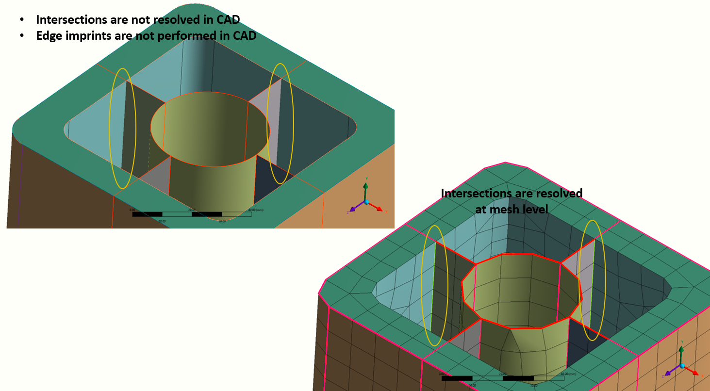
Shell mesh connections between sheet portions of the model can be resolved during meshing.
Simply define the desired element size, turn on Mesh-Based Connections and define the Connection Tolerance and Mesh Type as desired (or use the default and the software will both connect regions within the Connection Tolerance and generate the shell mesh when the mesh is generated).
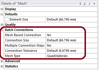
The Batch Connections settings are used to resolve gaps in the model.
 Want to learn more? If you are on Windows, go to
the documentation for this topic.
(Requires internet access and will
open in a new browser window. Not for Linux platforms.)
Analyses
Noise, Vibration, and Harshness (NVH) Analyses
Importing Surface Force Densities
Now, when you import a Surface Force Density load into a Mode Superposition Harmonic Response analysis, by default the load is applied using nodal forces via the new Load Application Type property. This new capability greatly reduces solution times.
 Want to learn more? If you are on Windows, go to
the documentation for this topic.
(Requires internet access and will
open in a new browser window. Not for Linux platforms.)
Improvements for the NVH Workflow for Electric Machines
Two new enhancements improve the NVH Workflow for Electric Machines:
- The Harmonic Acoustics analysis now provides a Step Controls category in the Analysis Settings if your analysis includes multiple RPM loading conditions. Each RPM load is considered as a load step, so you can now specify different frequency spacings, minimum frequencies, maximum frequencies, etc., for each load step.
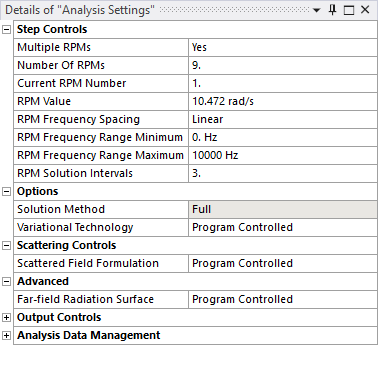
The new Step Controls for Harmonic Acoustics analyses.
- The Harmonic Acoustics analysis now supports post-processing Sound Power Level and Sound Pressure Level Microphone Waterfall diagrams to analyze acoustic radiation for a range of rotating conditions and frequencies.
 Want to learn more? If you are on Windows, go to
the documentation for this topic.
(Requires internet access and will
open in a new browser window. Not for Linux platforms.)
Waterfall Diagram Display Features
Waterfall Diagram results now provide options to add or remove probes on the diagram, as well as to specify lower and upper boundary values to redistribute the coloring on the chart.
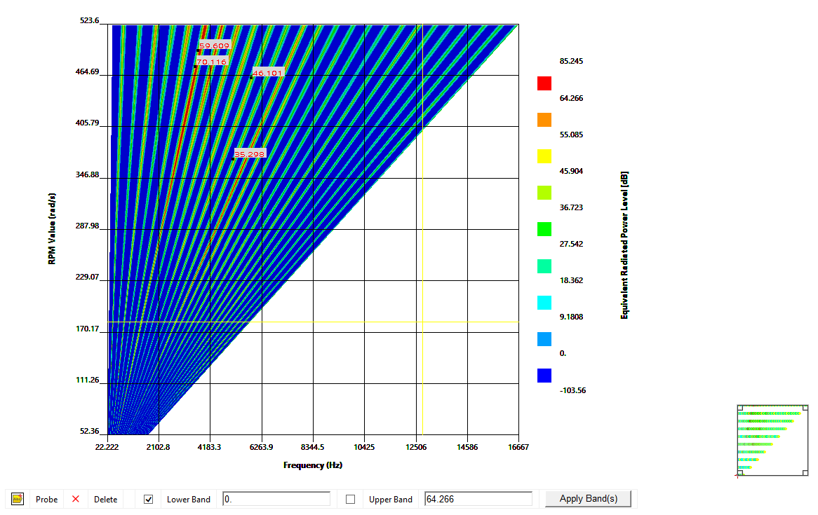
You now have more control over Waterfall Diagrams.
 Want to learn more? If you are on Windows, go to
the documentation for this topic.
(Requires internet access and will
open in a new browser window. Not for Linux platforms.)
Acoustics Analysis
One-way Acoustic Coupling Analysis
When performing a vibro-acoustic analysis between Harmonic Response and Harmonic Acoustics analyses, you now have the choice to import individual loading conditions, in the form of velocities, or to automatically import multiple loading conditions corresponding to the RPM (Rotations Per Minute) from the Harmonic Response analysis to the Harmonic Acoustics analysis.
 Want to learn more? If you are on Windows, go to
the documentation for this topic.
(Requires internet access and will
open in a new browser window. Not for Linux platforms.)
User Defined Result - Acoustic Intensity
You can now create a User Defined result for element nodal acoustic intensity.
 Want to learn more? If you are on Windows, go to
the documentation for this topic.
(Requires internet access and will
open in a new browser window. Not for Linux platforms.)
Modal Acoustics Damping Controls
A new Damping Control property is available for Modal Acoustic (stand-alone or pre-stressed) analyses. The Ignore Acoustic Damping property lets you ignore the damping effects created by material properties (Specific Heat, Thermal Conductivity, and Viscosity). Ignoring the damping effects enables the application to use undamped eigensolvers without the need to suppress these material properties in Engineering Data.
 Want to learn more? If you are on Windows, go to
the documentation for this topic.
(Requires internet access and will
open in a new browser window. Not for Linux platforms.)
Acoustics Data Export
Mechanical now enables you to export Power Level and other Waterfall diagram results to VREXPERIENCE Sound Pro software for sound synthesis, sound design, or psychoacoustics analysis.
 Want to learn more? If you are on Windows, go to
the documentation for this topic.
(Requires internet access and will
open in a new browser window. Not for Linux platforms.)
Additive Manufacturing
Additive Wizard
The Additive Wizard has been significantly enhanced to include:
- The option of meshing with a Layered Tetrahedral mesh or Cartesian mesh.
- Modeling of symmetrical parts.
- Simulation of powder elements.
- Simulation of non-build elements.
- The option to add a heat treatment step.
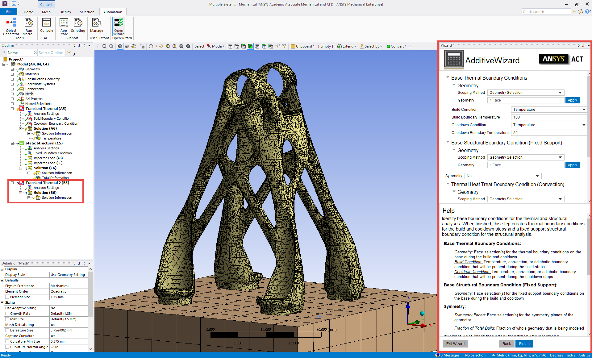
Additive Wizard showing a model with a layered tet mesh and a heat treatment step.
 Want to learn more? If you are on Windows, go to
the documentation for this topic.
(Requires internet access and will
open in a new browser window. Not for Linux platforms.)
Supports from .stl Files
You can now insert supports directly from .stl files at any time prior to simulation, separate from the part geometry. This feature is designed specifically for volume-less type of supports such as those from Additive Prep.
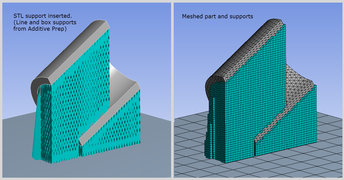
Volume-less support (in blue) from an .stl file. The support's voxel hex mesh and the part's layered tet mesh both respect the additive layers, as shown on the right.
 Want to learn more? If you are on Windows, go to
the documentation for this topic.
(Requires internet access and will
open in a new browser window. Not for Linux platforms.)
AM Process Sequencer
The AM Process Sequencer includes a new user step that can be added prior to the build step—to simulate bolt pretension, for example. The new drop-down option called User Step Prior to Build places a user step before the Static Structural steps. Previously, you needed to use a Commands object for this.
In addition, the AM Process steps are now much more identifiable in the Graph window under Analysis Settings and in Tabular Data under the Solution object:
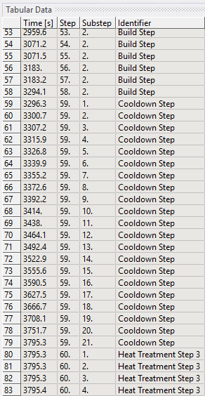
New labels (right column) more clearly identify the sequence steps in the additive simulation.
 Want to learn more? If you are on Windows, go to
the documentation for this topic.
(Requires internet access and will
open in a new browser window. Not for Linux platforms.)
Topology Optimization
Level Set Based Optimization Method
The Topology Optimization analysis provides a new optimization method: Level Set Based Optimization. This new Optimization Type enables you to directly deal with the boundary of a shape to deliver an unambiguous solution.
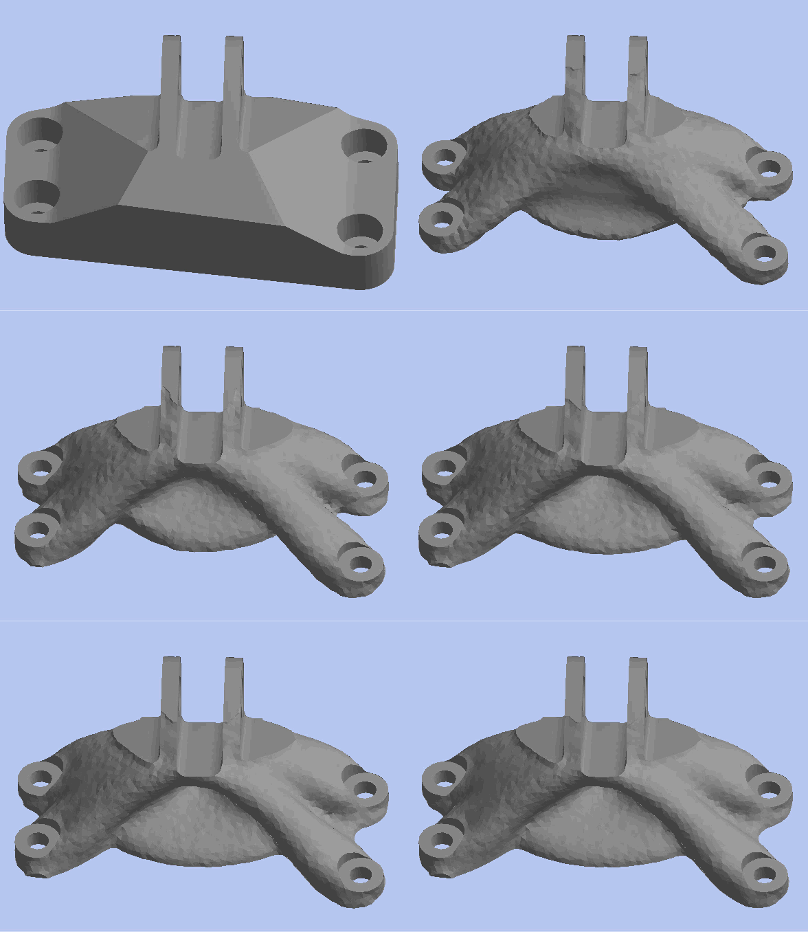
Level Set Based Optimization of a support bracket.

 Want to learn more? If you are on Windows, go to
the documentation for this topic.
(Requires internet access and will
open in a new browser window. Not for Linux platforms.)
Lattice Optimization Analysis
The Lattice Optimization method for Topology Optimization analyses now supports the Linux operating system.
Topology Optimization Reaction Force
The Reaction Force constraint has a new property: Criteria. The Reaction Force constraint enables you to make sure that your optimized geometry always supports a specified maximum reaction force. Using this new property, you can select whether to specify the maximum value (a) based on the summation of the reaction forces from all the selected nodes or (b) based on the normalized value of the reaction force extracted from each selected node. Options for the property include Sum Maximum (default) and Normalized Maximum.
 Want to learn more? If you are on Windows, go to
the documentation for this topic.
(Requires internet access and will
open in a new browser window. Not for Linux platforms.)
Combining Structural and Thermal Analyses
Topology optimization now supports the optimization of combined Static Structural and Steady-State Thermal analyses. This implies that Compliance and Thermal Compliance together can be applied as an Objective. Furthermore, the structural constraints (Global Von-Mises, Local Von-Mises, Displacement, and Reaction Force) and thermal constraint (Temperature) can be applied together for optimization.
 Want to learn more? If you are on Windows, go to
the documentation for this topic.
(Requires internet access and will
open in a new browser window. Not for Linux platforms.)
Parameterization
The following properties can now be parameterized during Topology Optimization analyses:
- Overhang Angle (AM Overhang Constraint)
- Analysis Settings:
- Maximum Number of Iterations
- Minimum Normalized Density
- Convergence Accuracy
- Penalty Factor
 Want to learn more? If you are on Windows, go to
the documentation for this topic.
(Requires internet access and will
open in a new browser window. Not for Linux platforms.)
Analysis Settings
Nonlinear Controls
Mechanical now provides a Program Controlled option for the Stabilization property of the Nonlinear Controls of the Analysis Settings. This new option is the default setting for the property and enables the Mechanical APDL solver to specify the appropriate Stabilization setting.
 Want to learn more? If you are on Windows, go to
the documentation for this topic.
(Requires internet access and will
open in a new browser window. Not for Linux platforms.)
Output Controls
For the Mechanical APDL solver, Mechanical now provides the following new Output Controls that enable finer control over what type of quantities are written to the result file. These options can help reduce the result file size if any of these output quantities are not needed for post-processing:
- Surface Stress
- Back Stress
- Contact Data
- Nonlinear Data
- Heat Generation Rate
- Element Current Density
- Electromagnetic Nodal Forces
- Result File Compression
 Want to learn more? If you are on Windows, go to
the documentation for this topic.
(Requires internet access and will
open in a new browser window. Not for Linux platforms.)
Damping Controls
The following Damping Controls properties have been updated:
Constant Structural Damping Coefficient Modal analyses support the Constant Structural Damping Coefficient property for the Solver Type settings Reduced Damped, Full Damped, Unsymmetric, and Program Controlled. The Program Controlled option is available when the selected solver is Reduced Damped, Full Damped, or Unsymmetric.
Equivalent Damping Ratio From Modal MSUP Harmonic Response and MSUP Transient analyses can now ignore the Material Dependent Damping ratio specified for the materials in Engineering Data by using the No option for the Eqv Damping Ratio from Modal property. This option can now be used to perform MSUP Harmonic and MSUP Transient analysis with Modal solution using Reduced Damped Solver Type option and Store Complex Solution property set to No.
 Want to learn more? If you are on Windows, go to
the documentation for this topic.
(Requires internet access and will
open in a new browser window. Not for Linux platforms.)
Nonlinear Adaptivity Remeshing Controls
The Nonlinear Adaptivity Remeshing Controls category of the Analysis Settings object includes a new property: Aggressive Remeshing. This property enables you to specify that a mesh be created with improved shape metrics. Property options include On and Off (default).
 Want to learn more? If you are on Windows, go to
the documentation for this topic.
(Requires internet access and will
open in a new browser window. Not for Linux platforms.)
General Axisymmetric
The General Axisymmetric symmetry feature now supports the MPC contact formulation type.
 Want to learn more? If you are on Windows, go to
the documentation for this topic.
(Requires internet access and will
open in a new browser window. Not for Linux platforms.)
Loading and Support Conditions
System Coupling Region
A new boundary condition is available in Mechanical: System Coupling Region. This new option enables you to expose surface and volume regions for use in couplings to other products using System Coupling.
 Want to learn more? If you are on Windows,
go to the documentation for this topic.
(Requires internet access and
will open in a new browser window. Not for Linux platforms.)
Bolt Pretension
Using the new Solve Behavior property in the Advanced category of the Details view, you can now apply a pretension load to multiple bolts on your model using only one Bolt Pretension object. You no longer need to create multiple Bolt Pretension objects.
 Want to learn more? If you are on Windows,
go to the documentation for this topic.
(Requires internet access and
will open in a new browser window. Not for Linux platforms.)
Nonlinear Adaptive Region
The Nonlinear Adaptive Region condition now supports the following:
- MPC and Normal Lagrange (3D analyses as well) contact formulations.
- Materials that include the Mullins Effect material property.
 Want to learn more? If you are on Windows,
go to the documentation for this topic.
(Requires internet access and
will open in a new browser window. Not for Linux platforms.)
Graphics
Viewports
Now, when you are using the Viewports feature, you can synchronize all open windows to reorient or move (pan, zoom, rotate) your model in each window simultaneously.
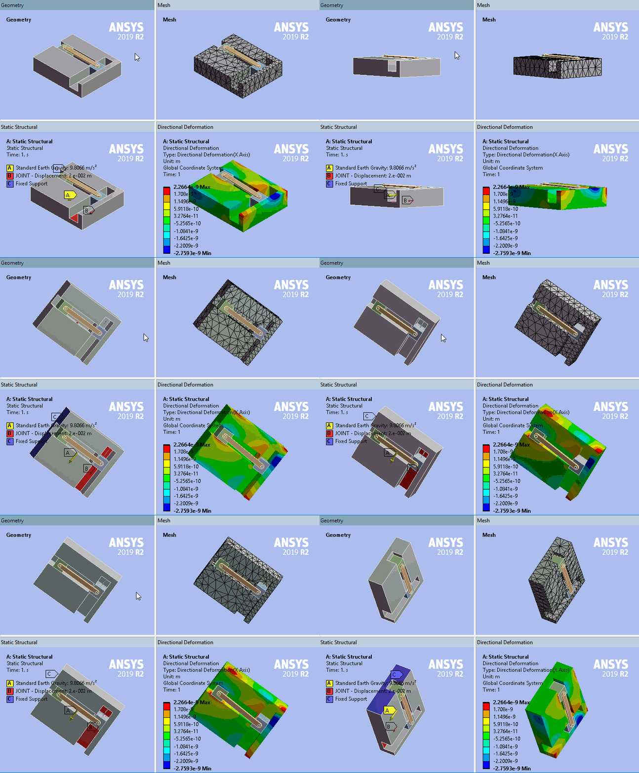
Synchronized model manipulation in multiple windows.
 Want to learn more? If you are on Windows, go to
the documentation for this topic.
(Requires internet access and will
open in a new browser window. Not for Linux platforms.)
Results Legend Display Options
There is a new annotation display option for results: Deformation Scale Factor. Available using the right-click (context) menu for the result legend displayed in the Geometry window, this option turns an annotation on or off for the current scaling menu selection.
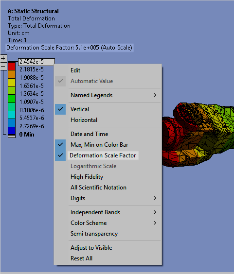
On/Off control of annotations.
 Want to learn more? If you are on Windows, go to
the documentation for this topic.
(Requires internet access and will
open in a new browser window. Not for Linux platforms.)
Additional Graphics Options
There are new options:
- for Animation legacy AVI, which has different behavior and features compared to the current AVI. Both behaviors are explained in the help.
- to change the number of Local min/max probes. Up to 20 are now supported instead of the previous six.
 Want to learn more? If you are on Windows, go to
the documentation for this topic.
(Requires internet access and will
open in a new browser window. Not for Linux platforms.)
Rotational Center Improvements
Rotational centers can now be placed on deformed results.
 Want to learn more? If you are on Windows, go to
the documentation for this topic.
(Requires internet access and will
open in a new browser window. Not for Linux platforms.)
Scripting Additions/Improvements
Manipulating Graphics
New Camera properties, Scene Width and Height, are more intuitive to use and can help achieve reproducible and predictable views across different simulations.
 Want to learn more? If you are on Windows, go to
the documentation for this topic.
(Requires internet access and will
open in a new browser window. Not for Linux platforms.)
Exporting Result or Probe Animations
New APIs have been added to allow export of animations to different video formats (MP4,WMV,AVI or GIF) with flexible settings (duration, frames, resolution, etc).
 Want to learn more? If you are on Windows, go to
the documentation for this topic.
(Requires internet access and will
open in a new browser window. Not for Linux platforms.)
Solution and Results
Frequency Display
For Modal Analyses with the Solver Type property (Analysis Settings) set to Full Damped, the Solution object provides a new property in the Post Processing category: Frequency Display. Options include Program Controlled (default) and All.
Setting the property to All enables the results evaluation to be carried out on all the frequencies extracted from the modal solution (that may or may not be a conjugate pair). This process increases the number of results sets and listings of the frequencies in the Tabular Data window even if you request a lower number of modes. When set to Program Controlled, the results evaluation treats complex frequencies as complex conjugate pairs. The Program Controlled option was the only option available in prior releases.
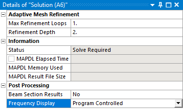
Frequency Display lets you choose between Program Controlled and All.
 Want to learn more? If you are on
Windows, go to the documentation for this topic.
(Requires internet
access and will open in a new browser window. Not for Linux platforms.)
Solution Combination
The Solution Combination feature now supports the combination of results from Random Vibration and Response Spectrum analyses.
In addition, the computational performance has been improved by a factor of 5.
 Want to learn more? If you are on
Windows, go to the documentation for this topic.
(Requires internet
access and will open in a new browser window. Not for Linux platforms.)
Accumulated Equivalent Plastic Strain
Mechanical has a new structural result type: Accumulated Equivalent Plastic Strain. This result enables you to sum the increments, per step, for Equivalent Plastic Strain results.
 Want to learn more? If you are on
Windows, go to the documentation for this topic.
(Requires internet
access and will open in a new browser window. Not for Linux platforms.)
External Model
Importing ABAQUS Composite Ply Data
You can now import composite ply data from ABAQUS Input (.inp) files.
 Want to learn more? If you are on Windows,
go to the documentation for this topic.
(Requires internet access and
will open in a new browser window. Not for Linux platforms.)
Imported Boundary Conditions
You can now import temperature data from NASTRAN Bulk Data (.bdf, .dat, .nas) files.
 Want to learn more? If you are on Windows,
go to the documentation for this topic.
(Requires internet access and
will open in a new browser window. Not for Linux platforms.)
New Supported Element Types
External Model now enables you to import the 3D Linear Triangle element CTRIA3 from NASTRAN Bulk Data files.
 Want to learn more? If you are on Windows,
go to the documentation for this topic.
(Requires internet access and
will open in a new browser window. Not for Linux platforms.)
Imported Named Selections
The NASTRAN commands BSURF and BSURFS are now supported and imported into Mechanical as element and element-face Named Selections.
 Want to learn more? If you are on Windows,
go to the documentation for this topic.
(Requires internet access and
will open in a new browser window. Not for Linux platforms.)
Contact and Connections
Contact Formulation
The MPC and Normal Lagrange (3D analyses as well) contact formulations are now supported with the use of the Nonlinear Adaptive Region.
 Want to learn more? If you are on
Windows, go to the documentation for this topic.
(Requires internet access
and will open in a new browser window. Not for Linux platforms.)
General
Key Assignments
Mechanical Hotkeys are now contained in the independent Key Assignments interface window. This window is accessible from the Tools group on the Home tab. It lists all the keyboard key and key combination shortcuts available in the application and includes an option to customize or edit the key assignments listed in the window.
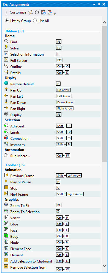
Key Assignments interface window.

 Want to learn more? If you are
on Windows, go to the documentation for this topic.
(Requires internet
access and will open in a new browser window. Not for Linux platforms.)
Saving and Restoring Interface Layouts
Users often take the time to position the various interface windows and panes of their simulation in a specific manner. You may hide certain windows and display others. You can now save your window layout configurations using the Store Layout option of the User Defined drop-down menu on the Home tab. This feature enables you to save multiple layouts, edit layouts, and delete layouts. In addition, the menu provides an option for you to restore the interface layout to the default setting.

Storage of window layouts.
 Want to learn more? If you are
on Windows, go to the documentation for this topic.
(Requires internet
access and will open in a new browser window. Not for Linux platforms.)
Adding an Interface Button
Mechanical now provides a feature that enables you to add Automation tab buttons that perform specific actions. Using the Manage option of the User Buttons group of the Automation tab, you can create, edit, and manage User Defined buttons.
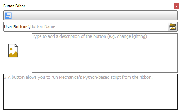
Adding Automation tab buttons
 Want to learn more? If you are
on Windows, go to the documentation for this topic.
(Requires internet
access and will open in a new browser window. Not for Linux platforms.)
Explicit Dynamics
Output Controls
Output Controls can be made step-aware in Explicit Dynamics analyses. You can decide if objects such as probes, trackers, and restart settings are controlled on a step-by-step basis (new) or globally (as before). Choosing step-awareness gives you the ability for finer control of your output reporting.
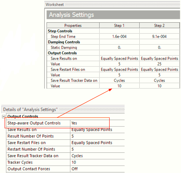
Output objects can be controlled on a step-by-step basis.
 Want to learn more? If you are on Windows, go to the documentation for this topic.
(Requires internet
access
and will open in a new browser window. Not for Linux platforms.)
Tabular Acceleration Input
A (single) acceleration object can be used to define an acceleration (applied to all bodies in the model) as tabular input:
- The acceleration (a vector quantity) can be input into the table in either vector or component form.
- The magnitude itself can be either a constant or a tabular quantity.
- The acceleration is step-aware—it can be turned on or turned off per component, per loadstep.
- The acceleration object can be in addition to a standard earth gravity object.
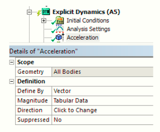
This acceleration object uses a vector description with the magnitude in tabular form.

The acceleration, scoped to all bodies, is step-aware.
 Want to learn more? If you are on Windows, go to the documentation for this topic.
(Requires internet
access
and will open in a new browser window. Not for Linux platforms.)
Rigid Body Dynamics
Three new joint types are available for Rigid Dynamics analyses: Constant Velocity Joint, Screw Joint, and Distance Joint.
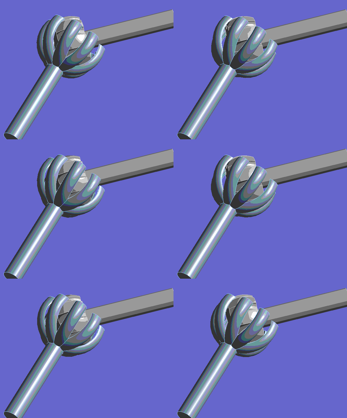
Constant Velocity Joint
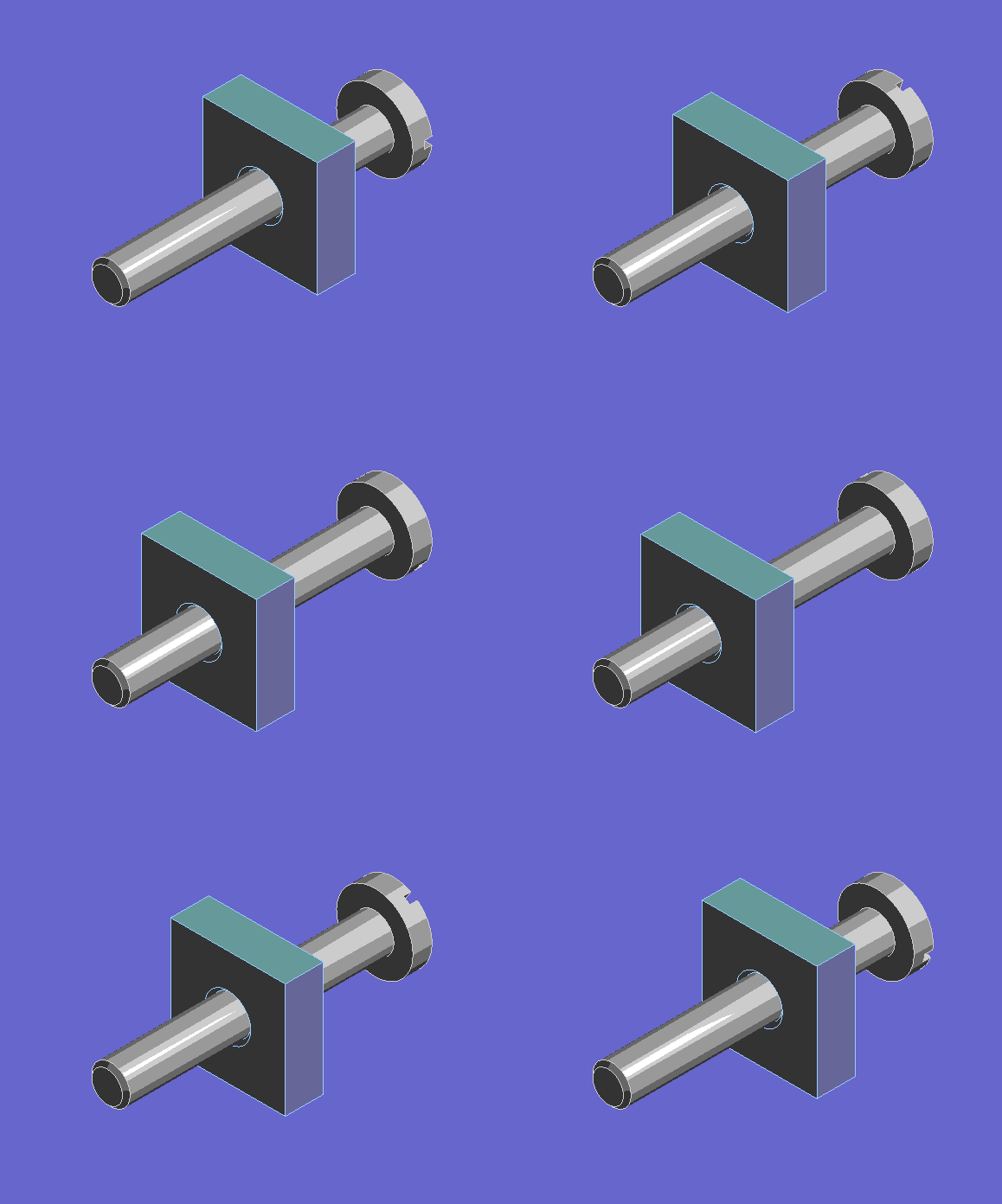
Screw Joint
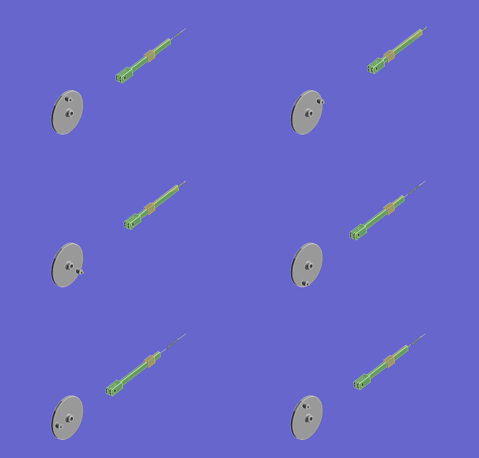
Distance Joint
 Want to learn more? If you are on Windows, go to the documentation for this topic.
(Requires internet
access
and will open in a new browser window. Not for Linux platforms.)
Hydrodynamic Interactions
The Offshore ACT extension (available as a Beta feature) exposes in Workbench the Mechanical APDL Ocean functionality, allowing you to calculate submerged beam loads due to various sea states in Mechanical's Static, Transient, Modal, and Harmonic Response analysis systems.
 Want to learn more? If you are on Windows, go to the documentation for this topic.
(Requires internet
access
and will open in a new browser window. Not for Linux platforms.)
Workbench LS-DYNA
Workbench LS-DYNA now supports Thick Shell elements.
 Want to learn more? If you are on Windows, go to the documentation for this topic.
(Requires internet
access
and will open in a new browser window. Not for Linux platforms.)
