
What's New in Mechanical at 2020 R1?
Play a video describing the new features:
Click any topic below for more information:
|
Usability and Interface Analysis Coupled Field Analyses Substructure Analysis |
Geometry and Connections Materials Loading and Boundary Conditions |
Results and Post Processing Additive Manufacturing |
|
Helpful Links These are for your convenience. They require internet access and will open in a new browser window. Some also require Customer Portal login credentials. |
|
"What's New" for Other Mechanical Releases Use these to easily see the "What's New" pages for other releases of Mechanical. Use these same links to return to this "What's New" page.
|
Mechanical Scripting Pane
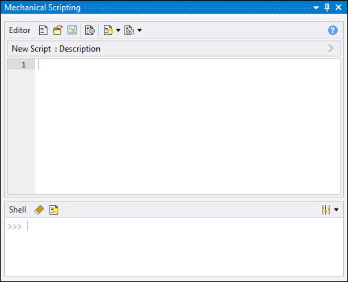
The ACT Console has been replaced by the new Mechanical Scripting pane. This new user interface pane:
-
Is easier to use and more efficiently organized.
-
Provides both a shell and a multi-line editor. Using this multi-line editor, you can develop and save scripts as files.
-
Enables you to promote Scripts to user buttons.
-
Supports the use of auto-complete.
 Want to
learn
more? If you are on Windows, go to the documentation for this topic.
(Requires internet access
and will open in a new browser window. Not for Linux platforms.)
Integrated Progress Bar
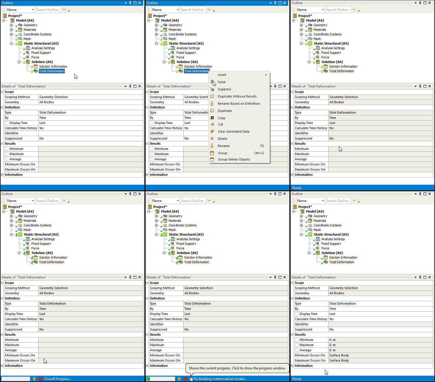
The Status Bar now displays the progress of application processes, such as mesh generation and solve, as well as the Interrupt and/or Stop options associated with these processes.
 Want to
learn
more? If you are on Windows, go to the documentation for this topic.
(Requires internet access
and will open in a new browser window. Not for Linux platforms.)
Design Validation for Topology Optimization
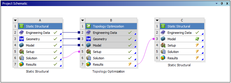
The Design Validation process for Topology Optimization now enables you to directly transfer your optimal faceted geometry to a Mechanical system on the Workbench Project page. The process automatically duplicates all the feeder systems and, when possible, automatically transfers and applies the scoping on the optimized shape. Because you do not need to import the optimized geometry into SpaceClaim using this direct workflow, the validation system no longer includes a Geometry cell.
 Want to
learn
more? If you are on Windows, go to the documentation for this topic.
(Requires internet access
and will open in a new browser window. Not for Linux platforms.)
Application-Based Transient Solution Settings
Transient solution settings based on your desired application can now be specified using the App. Based Settings property under the Solver Controls for Full Transient Structural analyses. Supported application options are listed below:
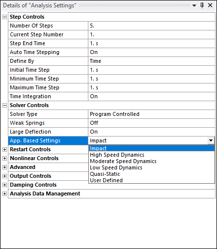
You can create your own transient parameters using the property’s User Defined option along with the Amplitude Decay Factor property. In prior releases, Amplitude Decay Factor was exposed as Numerical Damping Value under the Damping Controls for Full Transient Structural analyses.
 Want to
learn
more? If you are on Windows, go to the documentation for this topic.
(Requires internet access
and will open in a new browser window. Not for Linux platforms.)
On-Demand Expansion for Mode Superposition Solution Method
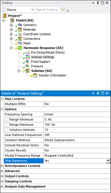
For Harmonic Response and Transient Structural analyses that are using the Mode Superposition Solution Method, there is a new Options Category property in the Analysis Settings: Skip Expansion. This property enables you to:
-
Reduce solution time and I/O by skipping the expansion phase when writing the solution result file. Solution times can be vastly improved, especially for models with many frequency or time steps.
-
Perform result calculations "on demand." This greatly reduces result evaluation times.
 Want to
learn
more? If you are on Windows, go to the documentation for this topic.
(Requires internet access
and will open in a new browser window. Not for Linux platforms.)
Output Controls
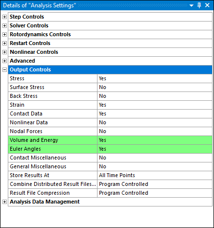
When you are using the Mechanical APDL solver, Mechanical now provides two new Output Controls:
-
Euler Angles
-
Volume and Energy
These options enable finer control on what type of quantities are requested to be written to the result file as well as help reduce the result file size if certain output quantities are not need for post-processing.
 Want to
learn
more? If you are on Windows, go to the documentation for this topic.
(Requires internet access
and will open in a new browser window. Not for Linux platforms.)
Using an Imported Load as an Initial Condition
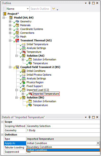
Now, when you import a Temperature load from the External Data system into a Coupled Field Transient analysis, a new Apply As property is available. Using this property, you can apply the load as either a Boundary Condition (default) or an Initial Condition. The Initial Condition option applies the load from the External Data system as an initial condition on the scoped geometry or mesh.
 Want to
learn
more? If you are on Windows, go to the documentation for this topic.
(Requires internet access
and will open in a new browser window. Not for Linux platforms.)
New Capabilities and Enhancements
For the Coupled Field analysis types, Static and Transient, you can now:
-
Import finite element data from the External Model systems.
-
Specify the Coupling and Constraint Equation conditions.
-
Apply a Spot Weld as a structural connection or as a thermal connection.
-
Specify the Temperature Result Tracker to obtain Global Minimum and Global Maximum result values.
 Want to
learn
more? If you are on Windows, go to the documentation for this topic.
(Requires internet access
and will open in a new browser window. Not for Linux platforms.)
Response Spectrum Support
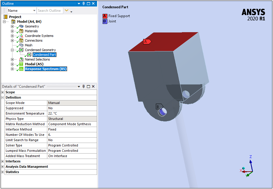
The Condensed Part feature to define substructures now supports the Response Spectrum analysis.
 Want to
learn
more? If you are on Windows, go to the documentation for this topic.
(Requires internet access
and will open in a new browser window. Not for Linux platforms.)
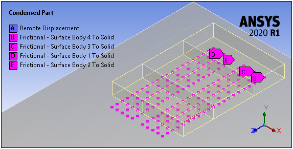
Contact Trim
Condensed Parts now support the use of the Trim Contact property. Using this property, you can trim the contact nodes on the interface and use the trimmed nodes as the Master Degrees of Freedom for the generation pass. The reduction of the number of nodes improves the performance of the generation pass. And, as illustrated, when you select the Condensed Part object after the generation pass, the application displays the trimmed nodes in the Geometry window for the Contact Region Interface instead of the actual Contact Region scoping.
 Want to
learn
more? If you are on Windows, go to the documentation for this topic.
(Requires internet access
and will open in a new browser window. Not for Linux platforms.)
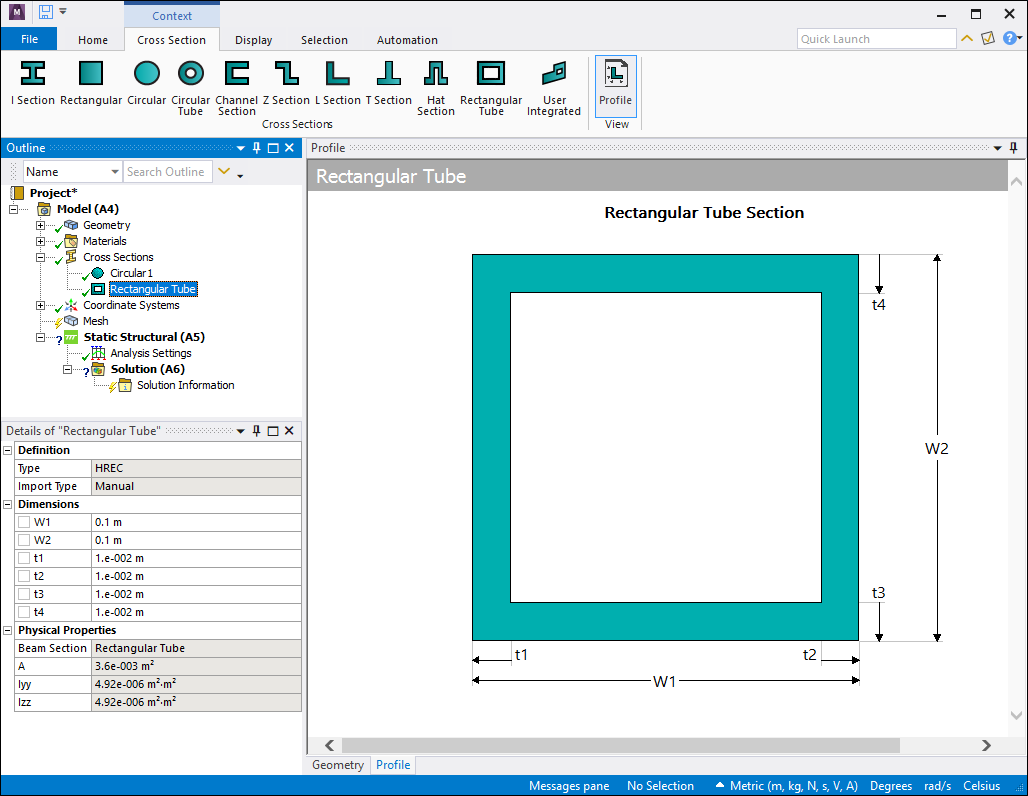
Create, Modify, and View Cross Sections
The Cross Sections feature has been significantly expanded, you can now:
-
Modify the dimensions of imported cross sections.
-
Create and parameterize your own cross sections for given types using the new Cross Section Context tab.
-
Display cross section and its dimensions using the Profile option.
 Want to
learn
more? If you are on Windows, go to the documentation for this topic.
(Requires internet access
and will open in a new browser window. Not for Linux platforms.)
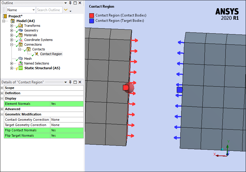
2D Edge Contact Display and Modification
For edge contacts on 2D surface bodies (only), there is a new Display category that includes the property Element Normals. This property enables the display of the normal direction of the elements for each edge in contact. You can use the Display feature in combination with the two new properties of the Geometric Modifications category: Flip Contact Normals and Flip Target Normals. These properties enable you to invert or flip the normal direction of the edge elements in contact.
 Want to
learn
more? If you are on Windows, go to the documentation for this topic.
(Requires internet access
and will open in a new browser window. Not for Linux platforms.)
Updating Contact Stiffness
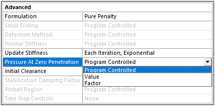
For the Contact Region object, there is a new option for the Update Stiffness property: Each Iteration, Exponential. This option updates stiffness using an exponential pressure-penetration relationship. In addition, when using this option, there are two new properties that become available:
| Pressure at Zero Penetration | Initial Clearance |
|---|---|
|
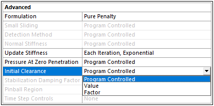 |
| The Pressure at Zero Penetration property corresponds to the PZER real constant used in the Mechanical APDL application. It defines the pressure when there is zero penetration between Contact and Target geometries. | The Initial Clearance property corresponds to the CZER real constant used in the Mechanical APDL application. It defines the initial clearance or gap at which the contact pressure begins to act on the Contact and Target geometries. |
 Want to
learn
more? If you are on Windows, go to the documentation for this topic.
(Requires internet access
and will open in a new browser window. Not for Linux platforms.)
Contact Splitting
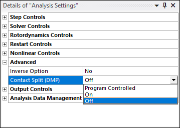
The Advanced category of the Analysis Settings object now includes the property Contact Split (DMP). This property enables you to split the contact pairs during the solution to speed up the solution for distributed memory parallel run.
 Want to
learn
more? If you are on Windows, go to the documentation for this topic.
(Requires internet access
and will open in a new browser window. Not for Linux platforms.)
Thermo-Mechanical Fatigue Models
Engineering Data now supports the following new material properties for Thermo-Mechanical Fatigue:
-
Nonlinear Isotropic Hardening (Power Law and Voce Law)
-
Chaboche Kinematic Hardening with Static Recovery
-
Exponential Visco-Hardening (EVH) Viscoplasticity
-
Perzyna and Peirce Viscoplasticity
-
Multilinear Isotropic Hardening Static Recovery
-
Nonlinear Isotropic Hardening
-
Hill Yield
 Want to
learn
more? If you are on Windows, go to the documentation for this topic.
(Requires internet access
and will open in a new browser window. Not for Linux platforms.)
Load Application without Surface Effect Elements
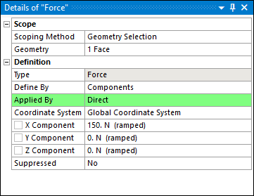
Now, when you specify a Pressure, Force, or Hydrostatic Pressure load on a 3D solid body, you can apply the loads directly onto faces, without creating surface effect elements, using the new Direct option of the Applied By property.
 Want to
learn
more? If you are on Windows, go to the documentation for this topic.
(Requires internet access
and will open in a new browser window. Not for Linux platforms.)
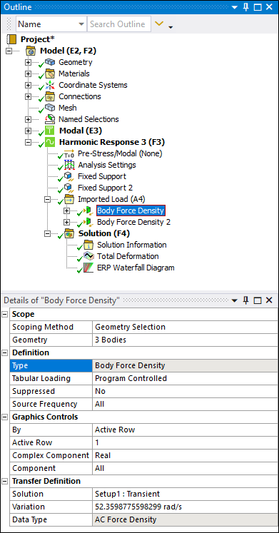
Importing Body Force Density Loads
To account for magnetostriction effects calculated in Maxwell, you can now import Body Force Density loads from the Maxwell application during Harmonic Response analyses.
 Want to
learn
more? If you are on Windows, go to the documentation for this topic.
(Requires internet access
and will open in a new browser window. Not for Linux platforms.)
Convection Load with Fluid Flow Display
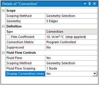
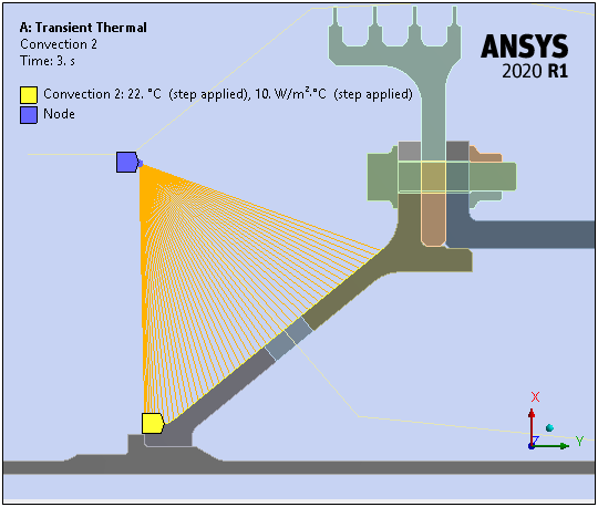
When you specify reference temperature using the Thermal Fluid property of a Line Body, and you set the Fluid Flow property of a Convection or Imported Convection Coefficient objects to Yes, there is a new display property: Display Connection Lines. This property enables the display of connection lines between the centroid of each element face/edge of the convection surface(s)/edge(s) to the corresponding closest node on the fluid flow scoping.
 Want to
learn
more? If you are on Windows, go to the documentation for this topic.
(Requires internet access
and will open in a new browser window. Not for Linux platforms.)
Nonlinear Adaptive Region
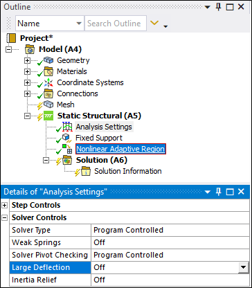
You can now use the Nonlinear Adaptive Region feature to improve solution accuracy in regions of high stress concentrations even when the Large Deflection property is set to Off.
 Want to
learn
more? If you are on Windows, go to the documentation for this topic.
(Requires internet access
and will open in a new browser window. Not for Linux platforms.)
Topology Optimization—User-Defined Criteria
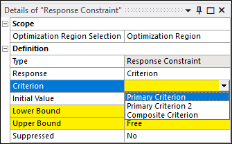
The Topology Optimization analysis has new result options: Primary Criterion and Composite Criterion, that enable you to define your own criteria for topology optimization.
Using the Primary Criterion option, you create averaged or maximum result values from a displacement nodal field...
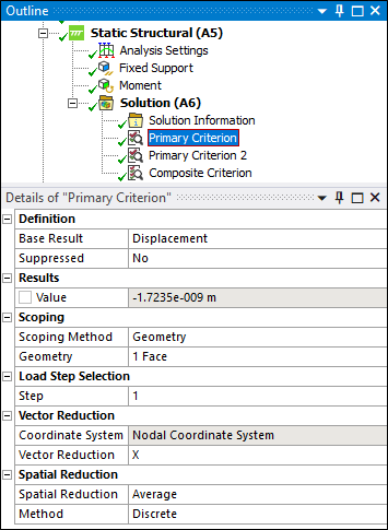
...and you combine Primary Criterion values into a single value using the Composite Criterion option.
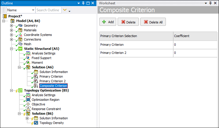
The Criterion values can be used as Response Constraint or Objective in a downstream Topology Optimization analysis.
 Want to
learn
more? If you are on Windows, go to the documentation for this topic.
(Requires internet access
and will open in a new browser window. Not for Linux platforms.)
Solution Combination
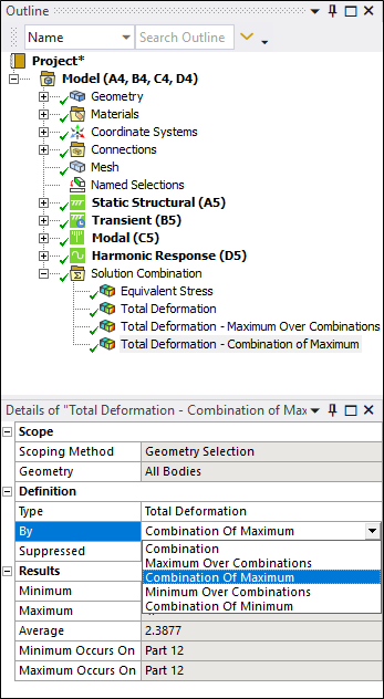
Results under Solution Combination have new result display options. You can now either examine a single desired Combination or choose one of these Envelope calculations:
-
Maximum Over Combinations or Combination of Maximum
-
Minimum Over Combinations or Combination of Minimum
 Want to
learn
more? If you are on Windows, go to the documentation for this topic.
(Requires internet access
and will open in a new browser window. Not for Linux platforms.)
Inherent Strain Method
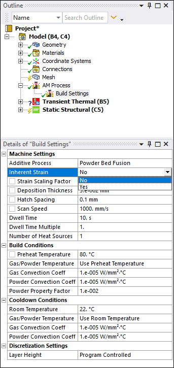
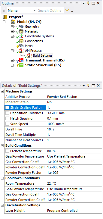
As an alternative to the thermal-structural additive process simulation, a new method using inherent strain is now available. This method requires a calibrated Strain Scaling Factor (SSF), similar to what is required for Additive Print.
 Want to
learn
more? If you are on Windows, go to the documentation for this topic.
(Requires internet access
and will open in a new browser window. Not for Linux platforms.)
Strain Scaling Factor for Thermal-Structural AM Simulations
You now have the option to use a Strain Scaling Factor (SSF) in a thermal-structural additive process simulation, to take advantage of machine/material calibrations.
 Want to
learn
more? If you are on Windows, go to the documentation for this topic.
(Requires internet access
and will open in a new browser window. Not for Linux platforms.)
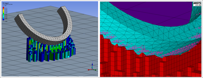
Tet-Mesh-to-Voxel-Mesh Connections Using AMCONNECT Macro
Making connections between a part meshed with layered tet mesh and STL Supports with a voxel mesh is now easier using a macro called AMCONNECT. This macro creates constraint equations between part and supports to connect the two.
 Want to
learn
more? If you are on Windows, go to the documentation for this topic.
(Requires internet access
and will open in a new browser window. Not for Linux platforms.)
Additive Wizard Enhancements
The Additive Wizard now includes:
-
The option to use the Inherent Strain method
-
ANSYS-provided additive materials automatically populated on the materials page of the wizard, eliminating the need to define engineering data in a separate step
-
The option to designate a sequential progression of cutoff operations of supports and/or baseplate
 Want to
learn
more? If you are on Windows, go to the documentation for this topic.
(Requires internet access
and will open in a new browser window. Not for Linux platforms.)
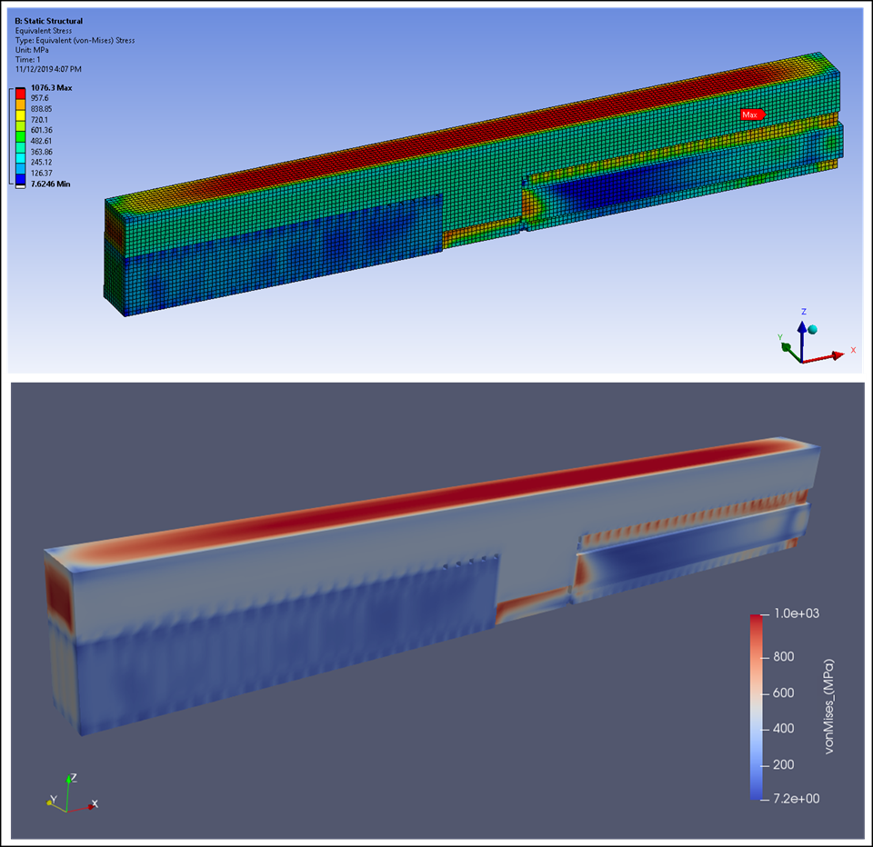
Additive-Print-to-Workbench-Additive Workflow for Support Cutoff
A new procedure is available if you want to use Mechanical to perform support cutoff, including defining a specific cutoff sequence, for simulations run in Additive Print.

 Want to
learn
more? If you are on Windows, go to the documentation for this topic.
(Requires internet access
and will open in a new browser window. Not for Linux platforms.)
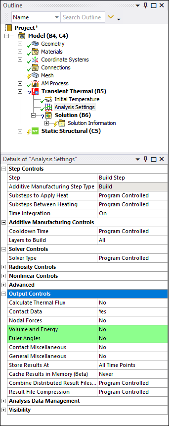
Reduced Result File Size
We have changed the default Output Controls (under Analysis Settings for the Transient Thermal analysis) to reduce the size of the result file. Specifically, the Euler Angles and Volume and Energy properties are set to No by default for Additive Manufacturing simulations.
 Want to
learn
more? If you are on Windows, go to the documentation for this topic.
(Requires internet access
and will open in a new browser window. Not for Linux platforms.)
